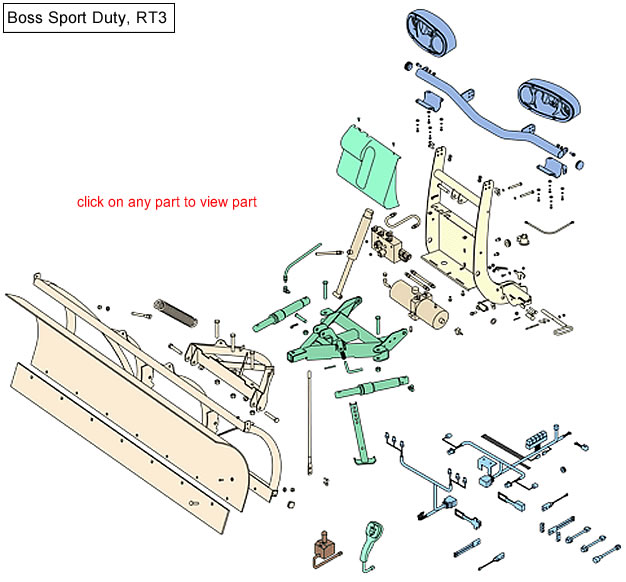
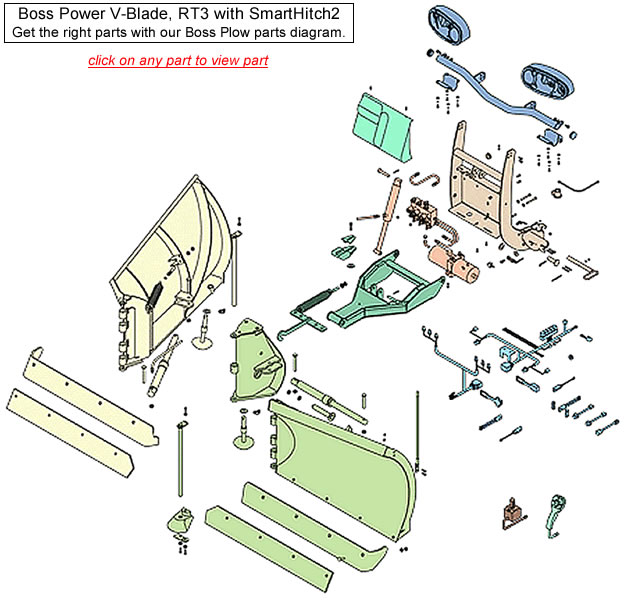
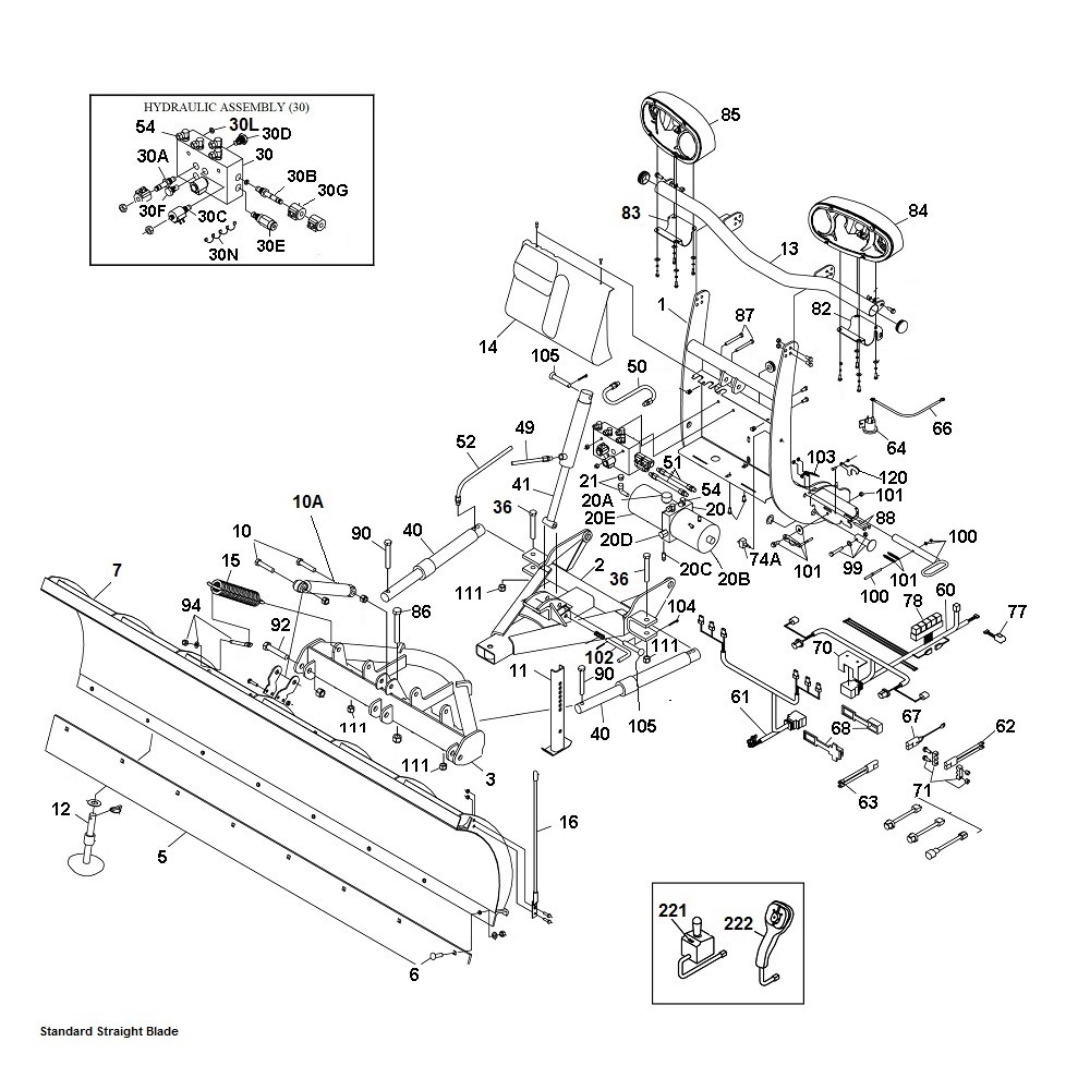
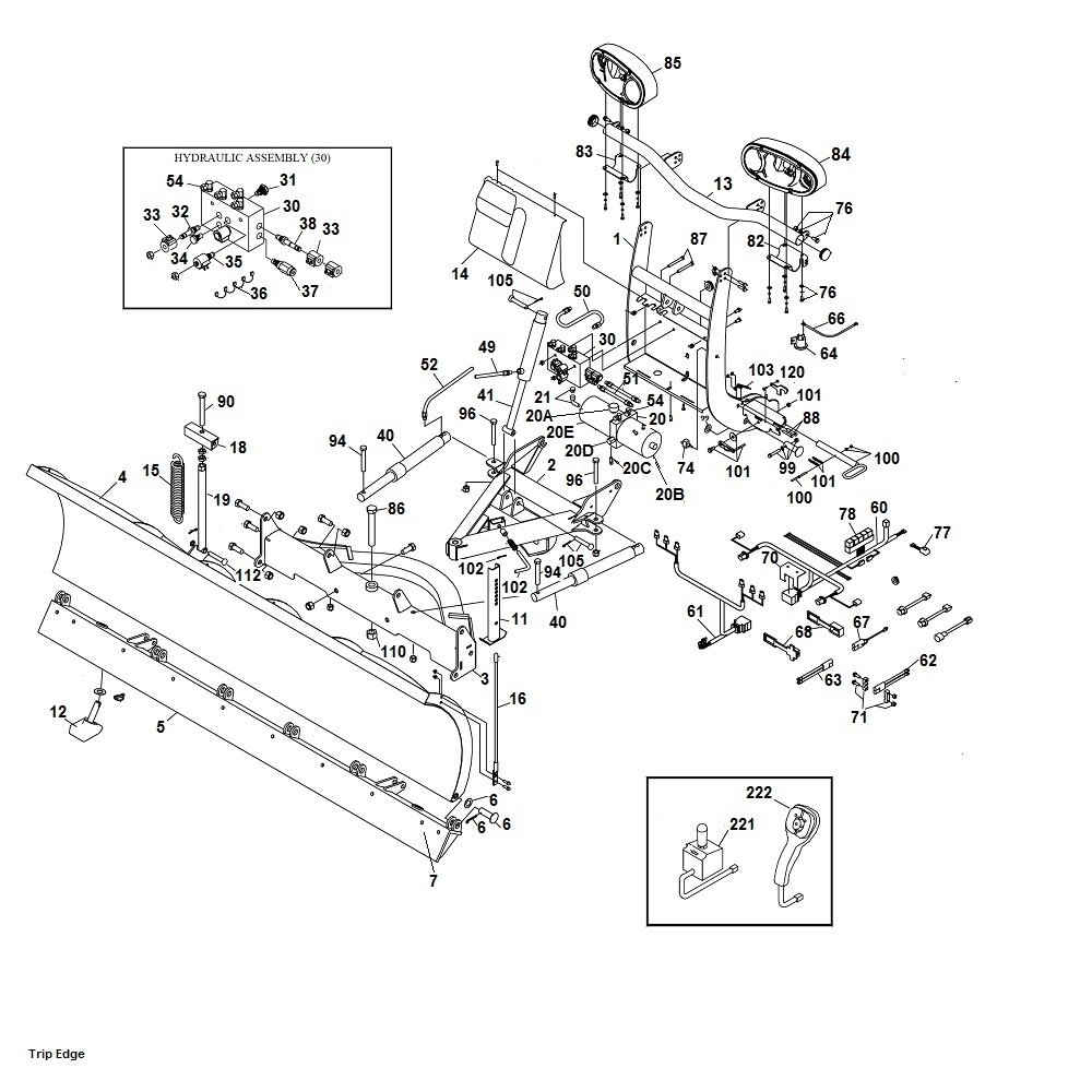
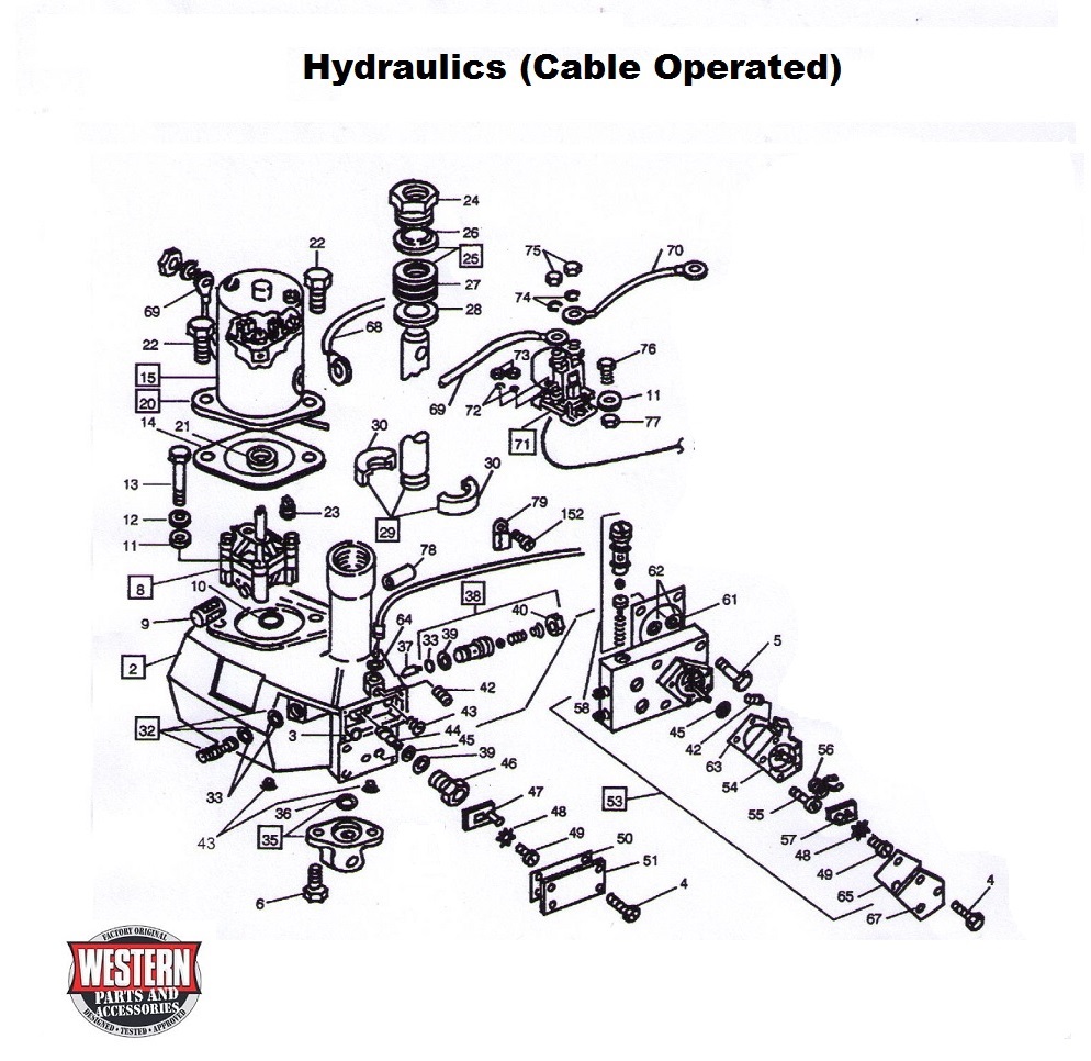
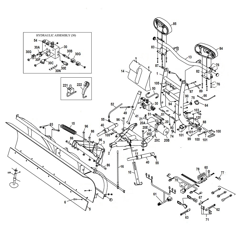
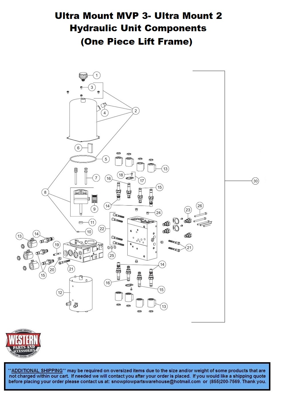
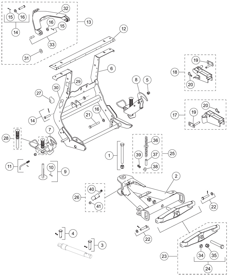
Hydraulic Boss V Plow Parts Diagram

Fill hydraulic pump reservoir to within from the top of the reservoir.
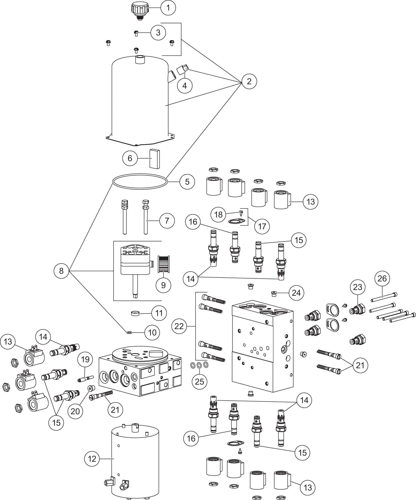
Hydraulic boss v plow parts diagram. Boss ldr box plow diagram. Part numbers and illustrations may vary. Hydraulic oil level. Fill the reservoir with boss high performance hydraulic fluid or equivalent.
Power v and straight blade snowplow owner s manual. Begin the assembly procedure by cutting down each corner of the plow box so that each wall of the box will lie flat on the floor. Boss snowplows detailed diagrams for snowplow parts and accessories. This manual is used for the installation of all v plows.
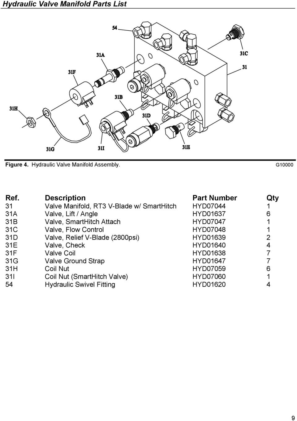
Hyd12280 parts assembly hyd12280 valve manifold layout hydraulic operation. Whenever you need service genuine boss parts or additional information contact an authorized service dealer. Power v blade straight blade history. Plow shoe wear.
Cutting edge wear. The top of the box can be used as a mat and will help prevent scratching the blade halves during installation. Boss power v dxt 10 w smarthitch2 diagram. Easily find the boss snowplow replacement parts you need.
Begin the assembly procedure by cutting down each corner of the plow box so that each wall of the box will lie flat on the floor. Power v manifold wiring diagram straight blade manifold wiring diagram power v wiring schematic. Boss power v dxt 8 2 9 2 w smarthitch2 diagram. Power v rt3 7 6 9 2 w smarthitch parts diagrams.
The box can be used as a mat and will help prevent scratching the blade halves during installation. Hydraulic driven air compressor parts accessories. To make the v shape with the plow press the left wing in and right wing in buttons simultaneously until the blades are fully retracted. Lay the top of the box flat on the floor.
Hydraulic cylinders for leakage rods for rust and pitting.

